Where a loft space is available, the installation method for the ceiling track will follow one of the below procedures. For loft space installation, it is physically possible to enter the loft and fix the ceiling track fixings on top of the joists, allowing simpler installation. The below fixing methods include tracks running parallel, perpendicular and diagonal to the joists.
It may be necessary to remove the loft floor boards if they are obstructing installation.
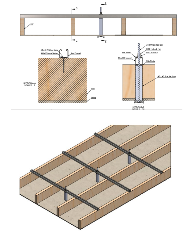
3.2.1 Ceiling Track running parallel with the Joists
This section will describe the process of fixing the ceiling track to the joists where the ceiling track is in parallel to the joist. It is not permitted for a single joist to suspend a track system, therefore during the ceiling marking out, section 3.1, the track should be positioned between two joists, at worst case, 2/3 towards one of the two joists.
Follow the process below for track installation
1. The installer must enter the loft space and locate the holes drilled into the ceiling between the joists.
2. Ensure that the located holes are central between the joists, this is important to spreading the load between two fixings.
3. Inspect the loft space for obstacles that may cause an issue to the installation of the steel channel.
4. Inspect the condition of the joists, ensure they are suitable and no damage that may cause an issue to safety or function to the joist is present. (e.g. Rotten, cracked)
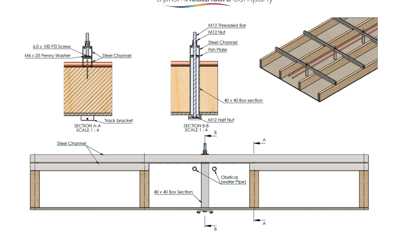
5. See section 3.1.4 for a solution on avoiding obstacles such as piping.
6. A piece of steel channel must be cut to length to span over four joists, with the track bracket installation in the centre.
7. Single-channel steel is sufficient when fixing ceiling track systems across joists.
8. Place the steel channel onto the four joists directly over the track bracket fixing point, refer to section 1.6 for information on how to even uneven joists.
9. Repeat step 7 for each track bracket fixing point.
10. Secure the steel channel to the joist using the 6×60 wood screws and an M6x25 penny washer.
11. Ensure to fix the steel channel at each joist, totalling four fixings per steel channel.
12. A piece of threaded bar must now be cut to length to suspend the track bracket from the steel channel to the ceiling. Each threaded bar will vary in length depending on the joist and ceiling height. Ensure to allow additional thread for the fixings.
13. A piece of 40×40 box section must be cut to length to fit from the bottom of the steel channel to the top face of the track bracket.
14. Insert the threaded bar through the steel channel, lock the threaded bar off at the top by placing a fish plate, full nut and nyloc nut onto the steel channel.
15. Place a fish plate up against the underside of the steel channel.
16. From the centre of the ceiling fixing hole, the 40×40 box section profile must be cut out.
17. Place the box section through the ceiling and onto the threaded bar, the box section should become flush with the steel channel and the ceiling.
18. Attach a track bracket (either a single 55mm threaded hole or a double 110mm bracket threaded hole depending whether the bracket is securing a single track or two joining tracks) to the end of the threaded bar, and secure with a M12 half nut at the ceiling end, applying Loctite 270 to the half nut.
19. The track bracket should become flush with the ceiling and box section.
Repeat all relevant steps to fit the next track bracket, and ensure the gap between the two fixings are suitable to the section 1.1.
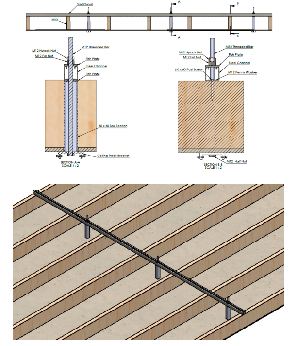
3.2.2 Ceiling Track running perpendicular to the Joists
This section will describe the process of fixing the ceiling track to the joists where the ceiling track is perpendicular to the joist.
Follow the process below for track installation.
1. The installer must enter the loft space and locate the holes drilled into the ceiling between the joists.
2. Inspect the loft space for obstacles that may cause an issue to the installation of the steel channel.
3. Inspect the condition of the joists, ensure they are suitable and no damage that may cause an issue to safety or function to the joist is present. (e.g. Rotten, cracked)
4. See section 3.1.4 for a solution on avoiding obstacles such as piping.
5. A piece of steel channel may be placed across the top of the joists, following the perpendicular path of the pre-drilled holes in the ceiling. There is no requirement to cut the steel channel unless it is necessary to avoid obstructions. Refer to section 1.6 for information on how to even uneven joists.
6. Single-channel steel is sufficient when fixing ceiling track systems across joists.
7. When using a steel channel, it may be necessary to use multiple pieces, ensure that the separate pieces are placed up against each other between joists where no fixings are located between.
8. Ensure that when the final ceiling track fixing point has been located (at both ends), the steel channel will span over an additional joist for increased strength.
9. Secure the steel channel to each joist using the 6×60 wood screws and an M6x25 penny washer.
10. A piece of threaded bar must now be cut to length to suspend the track bracket from the steel channel to the ceiling. Each threaded bar will vary in length depending on the joist and ceiling height. Ensure to allow additional thread for the fixings.
11. A piece of 40×40 box section must be cut to length to fit from the bottom of the steel channel to the top face of the track bracket.
12. Insert the threaded bar through the steel channel, lock the threaded bar off at the top by placing a fish plate, full nut and nylon nut onto the steel channel.
13. Place a fish plate up against the underside of the steel channel.
14. From the centre of the ceiling fixing hole, the 40×40 box section profile must be cut out.
15. Place the box section through the ceiling and onto the threaded bar, the box section should become flush with the steel channel and the ceiling.
16. Attach a track bracket (either a single 55mm threaded hole or a double 110mm bracket threaded hole depending whether the bracket is securing a single track or two joining tracks) to the end of the threaded bar, and secure with a M12 half nut at the ceiling end, applying loctite 270 to the half nut.
17. The track bracket should become flush with the ceiling and box section.
Repeat all relevant steps to fit the next track bracket, ensure the gap between the two fixings are suitable to the section 1.1.
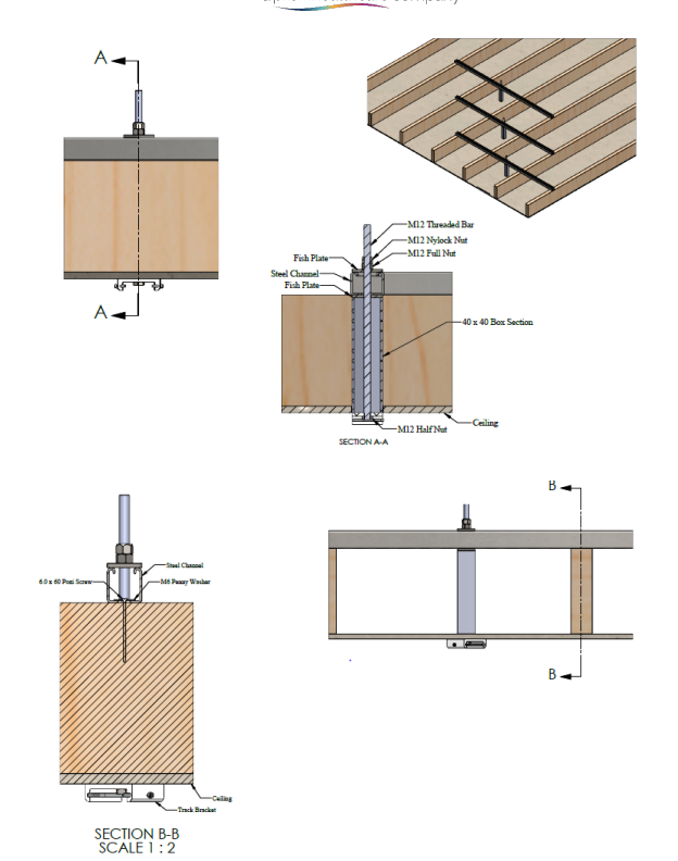
3.2.3 Ceiling Track running diagonal to the Joists
This section will describe the process of fixing the ceiling track to the joists where the ceiling track is diagonal to the joist.
Follow the process below for track installation.
1. The installer must enter the loft space and locate the holes drilled into the ceiling between the joists.
2. Inspect the loft space for obstacles that may cause an issue to the installation of the steel channel.
3. Inspect the condition of the joists, ensure they are suitable and no damage that may cause an issue to safety or function to the joist is present. (e.g. Rotten, cracked)
4. See section 3.1.4 for a solution for avoiding obstacles such as piping.
5. For each fixing, a piece of steel channel must be cut to length to span over four joists, with the track bracket installation in the centre.
6. Single-channel steel is sufficient when fixing ceiling track systems across joists.
7. Place the steel channel onto the four joists directly over the track bracket fixing point, refer to section 1.6 for information on how to even uneven joists.
8. Repeat step 7 for each track bracket fixing point. The steel channels should appear across the joists in a diagonal fashion, while the individual channels are perpendicular. (see image below)
9. Secure the steel channel to the joist using the 6×60 wood screws and an M6x25 penny washer.
10. Ensure to fix the steel channel at each joist, totalling four fixings per steel channel.
11. A piece of threaded bar must now be cut to length to suspend the track bracket from the steel channel to the ceiling. Each threaded bar will vary in length depending on the joist and ceiling height. Ensure to allow additional thread for the fixings.
12. A piece of 40×40 box section must be cut to length to fit from the bottom of the steel channel to the top face of the track bracket.
13. Insert the threaded bar through the steel channel, and lock the threaded bar off at the top by placing a fish plate, full nut and nyloc nut onto the steel channel.
14. Place a fish plate up against the underside of the steel channel.
15. From the centre of the ceiling fixing hole, the 40×40 box section profile must be cut out.
16. Place the box section through the ceiling and onto the threaded bar, the box section should become flush with the steel channel and the ceiling.
17. Attach a track bracket (either a single 55mm threaded hole or a double 110mm bracket threaded hole depending on whether the bracket is securing a single track or two joining tracks) to the end of the threaded bar, and secure with a M12 half nut at the ceiling end, applying Loctite 270 to the half nut.
18. The track bracket should become flush with the ceiling and box section.
Repeat all relevant steps to fit the next track bracket, ensure the gap between the two fixings are suitable to the section 1.1.
Within this section the fixing method for each individual fixing point is identical to that of section 3.2.1, only with the fixings moving diagonally within the loft space.
3.2.4 Joist fixing obstacles
This section will cover the best solutions to working fixings around obstacles such as pipes. Follow the process below for assistance in avoiding certain obstructions. The process below can be referred to when fixing a ceiling track into a loft space from either section 3.2.1, 3.2.2, and 3.2.3.
1. The installer must enter the loft space and locate the holes drilled into the ceiling between the joists.
2. Inspect the loft space for obstacles that may cause an issue to the installation of the steel channel.
3. It is found that the standard procedure of placing steel channel has been obstructed due to pipe works. Follow the steps below:
4. Between each joist where an obstruction is located, the height of the steel channel must be raised. This can be done by double layering steel channel.
5. Fix the first layer of steel channel across a minimum of two joists. This first layer will be fixed on either side of the obstructed path. (see image)
6. Secure the steel channel to the joists using the 6×60 wood screws and an M6x25 penny washer.
7. Ensure to fix the steel channel at each joist, totalling two fixings per steel channel.
8. Once the first layer has been fixed, the height of the bridging steel channel should have been increased and allow the steel channel to pass over the obstruction. (where the obstruction is still causing an obstruction – it is permitted to use a track spacer to increase the height of the first layer of steel channel a few millimetres.
9. Fix the bridging steel channel across all four joists, with the obstruction central. To fix the bridging steel channel, M12 threaded bar must be used.
10. Cut the threaded bar to length, it must pass through the two steel channels and allow enough length to secure the fixings.
11. A minimum of one threaded bar fixing should be installed to fix the two steel channels together on either side of the obstruction. (see image below). The bar should be inserted central between the joists.
12. Fix the two steel channels together with the threaded bar and secure in place with a fish plate and two half nuts on either side.
13. Once the steel channels have been installed, the track bracket fixing method must be continued.
14. A piece of threaded bar must now be cut to length to suspend the track bracket from the steel channel to the ceiling. Ensure to allow additional thread for the fixings.
15. A piece of 40×40 box section must be cut to length to fit from the bottom of the steel channel to the top face of the track bracket.
16. Insert the threaded bar through the steel channel, lock the threaded bar off at the top by placing a fish plate, full nut and nyloc nut onto the steel channel.
17. Place a fish plate up against the underside of the steel channel.
18. From the centre of the ceiling fixing hole, the 40×40 box section profile must be cut out.
19. Place the box section through the ceiling and onto the threaded bar, the box section should become flush with the steel channel and the ceiling.
20. Attach a track bracket (either a single 55mm threaded hole or a double 110mm bracket threaded hole depending whether the bracket is securing a single track or two joining tracks) to the end of the threaded bar, and secure with a M12 half nut at the ceiling end, applying Loctite 270 to the half nut.
21. The track bracket should become flush with the ceiling and box section.
Repeat all relevant steps to fit the next track bracket, ensure the gap between the two fixings are suitable to the section 1.1.
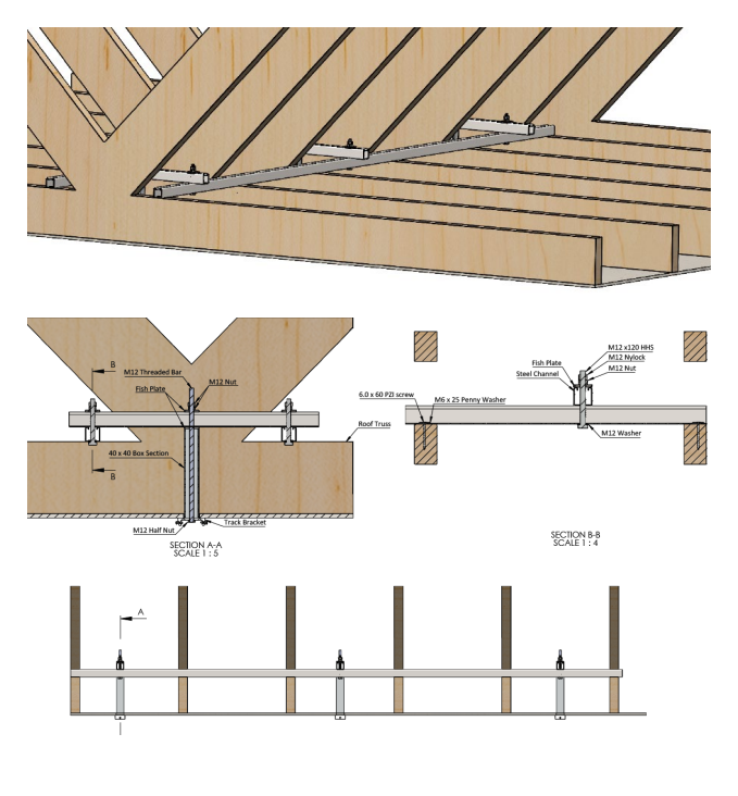
3.2.5 Ceiling Track Perpendicular with Trusses
This section will describe the best fixing process for a ceiling track system when the fixing positions are obstructed by ceiling trusses.
Follow the process below for track installation.
1. The installer must enter the loft space and locate the holes drilled into the ceiling between the joists.
2. Inspect the loft space for obstacles that may cause an issue to the installation of the steel channel.
3. It is found that the standard procedure of placing steel channels has been obstructed due to trusses.
Follow the steps below:
4. The method of fixing a steel channel has been obstructed due to trusses, therefore a new fixing point must be created. This can be done using two parallel steel channels, running on either side of the trusses and fixed from one joist to the next. These two steel channels will run parallel with the ceiling track.
5. Two pieces of steel channel on either side of the trusses may be placed across the top of the joists, following the perpendicular path of the pre-drilled holes in the ceiling. There is no requirement to cut the steel channel unless it is necessary to avoid obstructions. Refer to section 1.6 for information on how to even uneven joists.
6. Single-channel steel is sufficient when fixing ceiling track systems across joists.
7. When using a steel channel, it may be necessary to use multiple pieces, and ensure that the separate pieces are placed up against each other between joists where no fixings are located between.
8. Ensure that when the final ceiling track fixing point has been located (at both ends), the steel channel will span over an additional joist for increased strength.
9. Secure the steel channel to each joist using the 6×60 wood screws and an M6x25 penny washer.
10. With the two steel channels now in place, running parallel with the track direction. A steel channel must be used to bridge between the two parallel steel channels where the track bracket fixing points align.
11. When the spanning distance between the two parallel steel channels is between 250mm and 600mm, single steel channel is sufficient. Where the distance between the two steel channels is between 600mm and 1000mm, double steel channel is required. It is recommended that the distance between the two parallel steel channels is kept as narrow as possible.
12. To fix the bridging steel channel between the parallel channels, M12 threaded bar must be used.
13. Cut the threaded bar to length, it must pass through the two steel channels and allow enough length to secure the fixings.
14. The threaded bar should be fixed at both ends, securing the bridging steel channel.
15. Fix the two steel channels together with the threaded bar and secure in place with a fish plate and two half nuts on either side.
16. Once the steel channels have been installed, the track bracket can be installed onto the bridging steel channel, see the process below.
17. A piece of threaded bar must now be cut to length to suspend the track bracket from the steel channel to the ceiling. Ensure to allow additional thread for the fixings.
18. A piece of 40×40 box section must be cut to length to fit from the bottom of the steel channel to the top face of the track bracket.
19. Insert the threaded bar through the steel channel, lock the threaded bar off at the top by placing a fish plate, full nut and nyloc nut onto the steel channel.
20. Place a fish plate up against the underside of the steel channel.
21. From the center of the ceiling fixing hole, the 40×40 box section profile must be cut out.
22. Place the box section through the ceiling and onto the threaded bar, the box section should become flush with the steel channel and the ceiling.
23. Attach a track bracket (either a single 55mm threaded hole or a double 110mm bracket threaded hole depending on whether the bracket is securing a single track or two joining tracks) to the end of the threaded bar, and secure with a M12 half nut at the ceiling end, applying Loctite 270 to the half nut.
24. The track bracket should become flush with the ceiling and box section.
Repeat all relevant steps to fit the next track bracket, ensure the gap between the two fixings are suitable to the section 1.1.