For the correct procedure on fixing the parallel ceiling track, refer to the relevant ceiling track bracket and fixings installation process. This will depend on the type of material the h-system is being installed into. For concrete refer to section 2.0, for timber, refer to section 3.0.
Once track brackets have been installed, refer to section 8.0 for track installation.
When fixing the two-parallel track for an h-system, there are a few additional factors to consider:
The first factor that is essential for the function of the h-system is that the two tracks are perfectly parallel, this is important as the moving track in between jam if the distance between the two fixing where to increase or decrease along the system. It is also important to leave at least 250mm between one parallel track and the side wall to allow easier removal of hoist for servicing.
The second factor is the distance between the two parallel tracks. As the moving track will only be fixed to the two parallel tracks, the maximum span of the track must be considered. The moving track, track type must be considered depending on the spanning distance between its two fixings, and the chosen SWL to be applied to the track. See section 1.1 – straight track fixing requirements to ensure that the maximum span of the chosen track type is not exceeded.
Once the positions of the track system have been determined, the room must be assessed for obstacles. Refer to section 1.6 on ceiling track room assessment to ensure that the fixing of tracks is suitable. In addition to this, the following point must be considered: ensure that no obstacles will cause an issue to the fixing of the moving track between the two parallel, this can include obstacles such as projectors, low hanging light fixings etc. A clear traversing path must be available for the h-system.
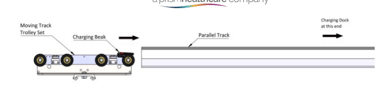
Another factor to consider are the h-system trolleys. The trolleys must be placed into the parallel tracks, during some cases of fixed track installation, the track can be fixed from one end of the room to the other, not allowing any space for the trolleys to be inserted afterwards. Always ensure to place the trolley into both parallel track systems before closing the track system off, either against the wall or before placing the end stop, end cap and safety bolt.
The trolley which includes the charging beak, must be align in the direction that the charging dock is fixed. (ensure that the trolley will dock into the charging dock at the chosen docking location) The other trolley can be inserted into the track in either orientations.
The installation of the h-system charging dock on the parallel track is the same as a typical charging dock would be. Refer to section hoist installation manual for parallel track charging dock installation.
8.1.1 Fixing the Charging Beak to the Trolley
One of the two trolleys will require the charging beak to be assembled onto the trolley. This trolley will be inserted into the parallel track where the (parallel) charging dock is located. To fix the charging beak, follow the procedure below:
1. Align the beak with the trolley fixing holes facing outward from the trolley centre.
2. Fix the beak using the given screws and secure with the two nyloc nuts on the back face.
3. Route the charging wire to the centre of the trolley and run the wire down the inside face of the trolley. (the face towards the moving track).
4. The wire can be secured in place by securing the provided cable ties through the fixing holes in the trolley.
5. The (moving track) charging dock can be allowed to hang for now and will be inserted into the moving track once the track is installed.
6. Insert the trolley into the parallel track.