Once the fixings have already been installed into the ceiling, either through the process of chemical resin or using Zykon fixings, there are a few ways of attaching the track bracket. This usually depends on the height from the concrete ceiling to the false ceiling. Follow the suitable guide for the installation at hand. This does not include turntable fixing. See section 7.3 for turntable installation.
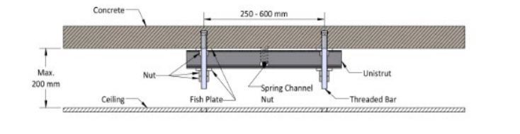
2.4.1 A False Ceiling with under 200mm Roof Space
Some buildings will have a very small roof space/void which will require the fixing method shown below. There is not enough roof space to create the solid structure within, therefore a threaded bar will suspend the track bracket directly from the height of the concrete ceiling. Follow the process below to secure the track bracket against the false ceiling.
1. When Zykon fixings have been used, two pieces of M12 threaded bars must be cut to a length, a suitable length to thread into the Zykon and fix a piece of steel channel and its fixings (fish plate and half nut).
2. For additional strength, Loctite 270 can be applied to the threaded bar where it threads into the Zykon.
3. Depending on the gap size between the two fixings, a piece of steel channel must be cut to a suitable length. If the gap size is between 250mm and 600mm, a single piece of steel channel will suit. If the gap size is between 600mm and 1000mm, a piece of double steel channel must be used and cut to a suitable length.
4. When placing the steel channel onto the threaded bars, ensure to place a spring channel nut into the steel channel and place it central. (this will be directly above the position of the track bracket on the false ceiling)
5. Fix the steel channel onto the two threaded bars and secure in place with a fish plate and half nut.
6. The steel channel should be flush with the concrete ceiling. (if the concrete is not level, place some M12 washers onto the threaded bar to level the steel channel)
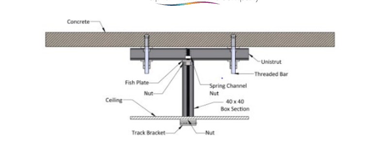
7. A piece of threaded bar can now be cut to length to reach from the spring channel nut to the false ceiling.
8. Insert the threaded bar into the spring channel washer. Lock in place with a fish plate up against the steel channel and a half nut to secure.
9. With the threaded bar protruding through the false ceiling, a 40×40 box section template can be cut out of the tile.
10. A piece of 40×40 box section must be cut to length to be placed onto the threaded bar and down to the ceiling height.
11. Thread the track bracket, either a single 55mm threaded hole or a double 110mm threaded hole (depending on the bracket requirement with the track) onto the threaded bar and up against the box section locking in place with a half nut.
12. When necessary, adjust the position of the bracket to make it level with the false ceiling using track spacers.
13. Repeat this process for each track bracket to complete track bracket installation.
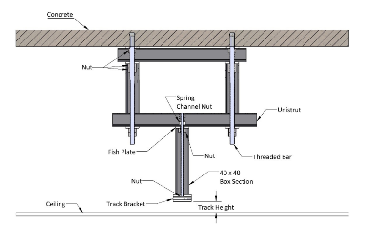
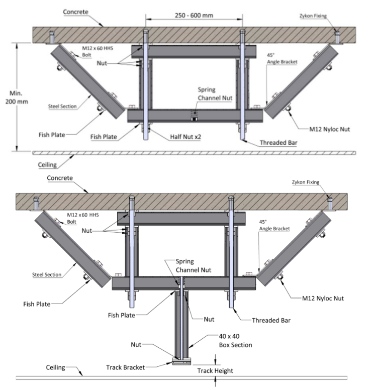
2.4.2 A False Ceiling with over 200mm Roof Space
When the roof space is over 200mm in height, the process below is the standard solution to creating a fixed solid structure from the concrete ceiling to the false ceiling, threaded bar with a length of over 200mm directly from a concrete ceiling to a false ceiling will allow too much swing in the track making it feel insecure. It must be strengthened using steel channel and box section. Follow the process below for a secure fixing of the track bracket against the false ceiling
1. When Zykon fixings have been used, two pieces of M12 threaded bars must be cut to length, a suitable length would be close to the height of the false ceiling.
2. For additional strength, Loctite 270 can be applied to the threaded bar where it threads into the Zykon.
3. Depending on the gap size between the two fixings, a piece of steel channel must be cut to a suitable length. If the gap size is between 250mm and 600mm, a single piece of steel channel will suit. If the gap size is between 600mm and 1000mm, a piece of double steel channel must be used and cut to a suitable length.
4. Fix the steel channel onto the two threaded bars and secure in place with a fish plate and two half nuts.
5. The steel channel should be flush with the concrete ceiling. (if the concrete is not level, place some M12 washers onto the threaded bar to level the steel channel)
6. Two pieces of 40×40 box section must be cut to a suitable length, these will be shorter than the threaded bars and allow enough space to place the box sections, steel channel and its fixings (fish plate and nut) onto the threaded bar.
7. Place the two box sections onto the two threaded bars and then secure them in position by placing the steel channel below.
8. When placing the steel channel onto the threaded bars, ensure to place a spring channel nut into the steel channel and place it central. (this will be directly above the position of the track bracket on the false ceiling)
9. Fix the steel channel onto the two threaded bars and secure in place with a fish plate and two half nuts.
10. The steel channel should be flush with the two box sections. (if the concrete ceiling is not level, place some M12 washers onto the threaded bar to level the two box sections)
11. Any excess threaded bar can be cut for tidy installation.
12. A piece of threaded bar can now be cut to length to reach from the spring channel nut to the false ceiling.
13. Insert the threaded bar into the spring channel washer. Lock in place with a fish plate up against the steel channel and a half nut to secure.
14. With the threaded bar protruding through the false ceiling, a 40×40 box section template can be cut out of the tile.
15. A piece of 40×40 box section must be cut to length to be placed onto the threaded bar and down to the ceiling height.
16. Thread the track bracket, either a single 55mm threaded hole or a double 110mm threaded hole (depending on the bracket requirement with the track) onto the threaded bar and up against the box section locking in place with a half nut.
17. When necessary, adjust the position of the bracket to make it level with the false ceiling using track spacers.
18. Repeat this process for each track bracket to complete track bracket installation.
2.4.3 A False Ceiling with over 500mm Roof Space
When the roof space is over 500mm in height, the process below is the standard solution to modifying the solid structure in 2.4.2 to provide additional lateral security to remove lateral movement. Follow the process below for a secure fixing of the track bracket against the false ceiling.
1. When Zykon fixings have been used, two pieces of M12 threaded bars must be cut to length, a suitable length would be close to the height of the false ceiling.
2. For additional strength, Loctite 270 can be applied to the threaded bar where it threads into the Zykon.
3. Depending on the gap size between the two fixings, a piece of steel channel must be cut to a suitable length. If the gap size is between 250mm and 600mm, a single piece of steel channel will suit. If the gap size is between 600mm and 1000mm, a piece of double steel channel must be used and cut to a suitable length.
4. Fix the steel channel onto the two threaded bars and secure in place with a fish plate and two half nuts.
5. The steel channel should be flush with the concrete ceiling. (if the concrete is not level, place some M12 washers onto the threaded bar to level the steel channel)
6. Two pieces of 40×40 box section must be cut to a suitable length, these will be shorter than the threaded bars and allow enough space to place the box sections, steel channel and its fixings (fish plate and nut) onto the threaded bar.
7. Place the two box sections onto the two threaded bars and then secure them in position by placing the steel channel below.
8. The steel channel below must be cut to a longer length to allow the 45° brackets to be fixed at both ends of the steel channel.
9. When placing the steel channel onto the threaded bars, ensure to place a spring channel nut into
the steel channel and place it central. (this will be directly above the position of the track bracket on the false ceiling)
10. Fix the steel channel onto the two threaded bars and secure in place with a fish plate and two half nuts.
11. The steel channel should be flush with the two box sections. (if the concrete ceiling is not level, place some M12 washers onto the threaded bar to level the two box sections)
12. Any excess threaded bar can be cut for tidy installation.
13. Onto both ends of the lower steel channel, the 45° bracket must be fixed.
14. The brackets can be fixed using an M12x60 bolt, and a fish plate and two half nuts on either side. Repeat this for both brackets on either side of the steel channel.
15. Two more 45° brackets must be fixed to the ceiling, these must be fixed using zykon fixings or chemical resin, mark out the fixing location using the bracket and follow the correct concrete fixing method (section 2.2 and/or 2.3) provide a fixing for the bracket.
16. Depending on the fixing method, follow the method below to fix the bracket:
17. (chemical resin) – secure the 45° bracket to the threaded bar using two half nuts. Cut of excess bar for tidy installation.
18. (Zykon) – insert a threaded bar into the Zykon fixing, ensuring the length is adequate for the installation. Secure the 45° bracket using to half nuts. Cut any excess bar for tidy installation.
19. Cut two pieces of steel channel that will span the distances between the 45° brackets on either side of the box section assembly.
20. Fix the steel channel to the brackets using an M12x60 bolt, and a fish plate and two half nuts on either side. The steel channel should be at a 45° angle. Ensure to repeat this for both sides of the box assembly. See the images below for reference.
21. A piece of threaded bar can now be cut to length to reach from the spring channel nut to the false ceiling.
22. Insert the threaded bar into the spring channel washer. Lock in place with a fish plate up against the steel channel and a half nut to secure.
23. With the threaded bar protruding through the false ceiling, a 40×40 box section template can be cut out of the tile.
24. A piece of 40×40 box section must be cut to length to be placed onto the threaded bar and down to the ceiling height.
25. Thread the track bracket, either a single 55mm threaded hole or a double 110mm threaded hole (depending on the bracket requirement with the track) onto the threaded bar and up against the box section locking in place with a half nut.
26. When necessary, adjust the position of the bracket to make it level with the false ceiling using track spacers.
27. Repeat this process for each track bracket to complete track bracket installation.
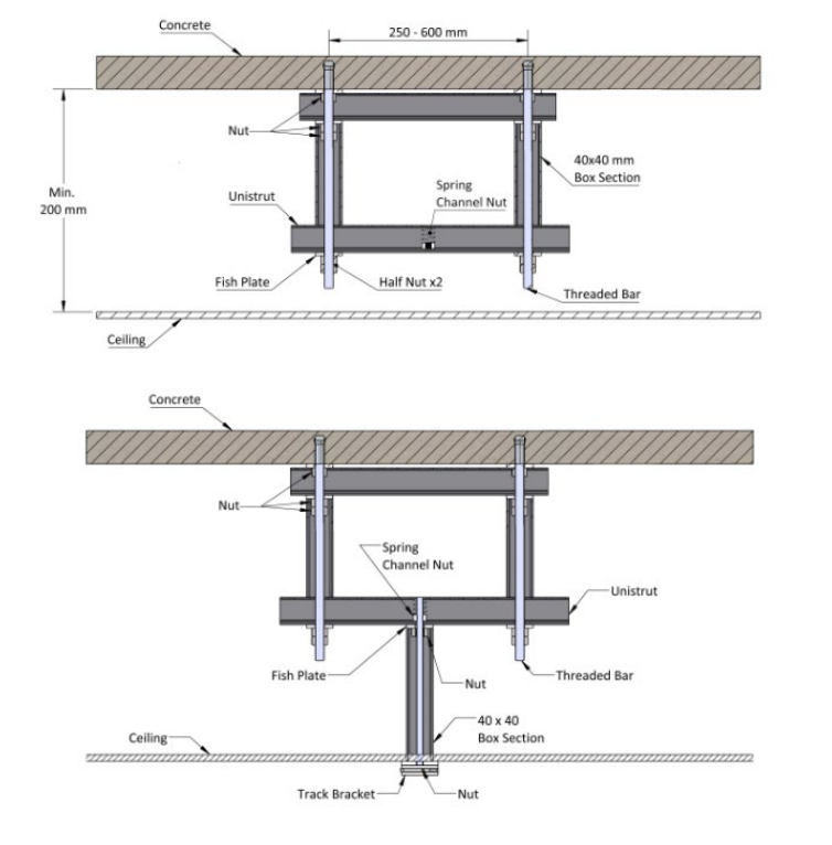
2.4.4 Lowered Track Requirements
When the track is required to be lowered from the ceiling, the two methods above will vary slightly. Follow the relevant section above (2.4.1, 2.4.2 or 2.4.3) for the initial fixing of the box section assembly. But to fix the track bracket the fixing method is stated below.
1. A piece of threaded bar must be cut to length from the spanning steel channel up to the desired track bracket height. (allowing additional thread for the bracket and half nut.)
2. Fix the threaded bar into the spring channel nut and secure with a fish plate and half nut.
3. With the threaded bar protruding through the false ceiling, a 40×40 box section template can be cut out of the tile.
4. A piece of white 40×40 box section must be cut to length to be placed onto the threaded bar and down to the chosen track bracket height.
5. Thread the track bracket, either a single 55mm threaded hole or a double 110mm threaded hole (depending on the bracket requirement with the track) onto the threaded bar and up against the box section locking in place with a half nut.
6. When necessary, adjust the position/height of the bracket using track spacers.
7. Repeat this process for each track bracket to complete track bracket installation.
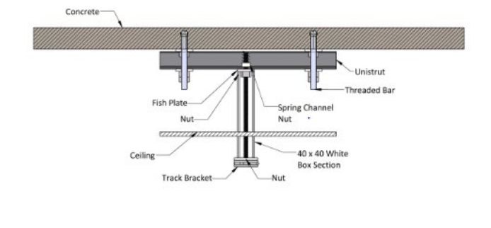
2.4.5 Inset Track Requirements
When an inset track is being installed into the ceiling, there is slight differences made to the installation process. Follow the relevant section above (2.4.1, 2.4.2 or 2.4.3) for the initial fixing of the box section assembly. But to fix the track bracket the fixing method is stated below. The track bracket will be suspended inside the false ceiling, depending on the track type used, the bracket will be suspended the height of the track to the false ceiling.
1. A piece of threaded bar must be cut to length from the spanning steel channel up to the track bracket height. (allowing additional thread for the bracket and half nut.). This will depend on the insert track type used. For single track inset track, the height of the bracket above the false ceiling will be 64mm. For the heavy duty track inset track the height will of the bracket above the false ceiling will be 176mm.
2. Fix the threaded bar into the spring channel nut and secure with a fish plate and half nut.
3. A piece of 40×40 box section must be cut to length to be placed onto the threaded bar and down to the chosen track bracket height.
4. Thread the track bracket, either a single 55mm threaded hole or a double 110mm threaded hole (depending on the bracket requirement with the track) onto the threaded bar and up against the box section locking in place with a half nut.
5. When necessary, adjust the position/height of the bracket using track spacers.
6. Repeat this process for each track bracket to complete track bracket installation.