See below the assembly instructions of the transition gate onto the three tracks. Follow each step in sequence to ensure correct assembly.
9.1.1 Fixed Track Transition Gate Assembly (Standard Transition Gate)
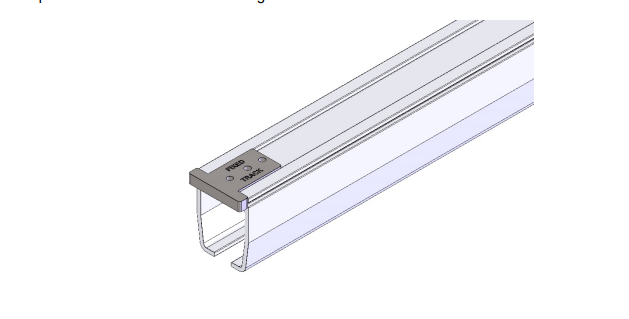
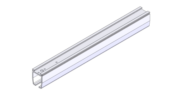
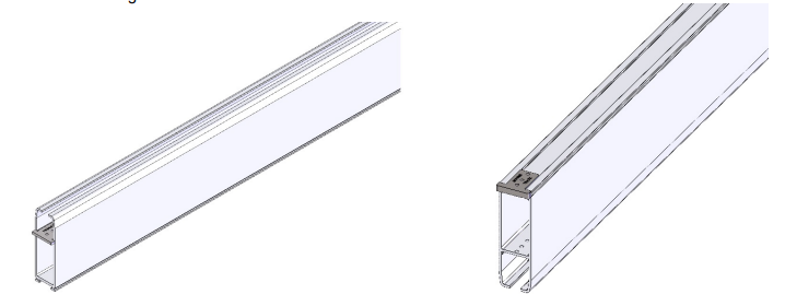
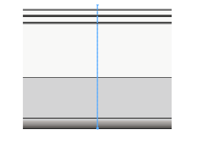
Starting with the fixed track piece, a template piece with “fixed track” engraved onto it must be placed on the top of the track as shown in the image below.
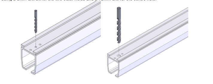
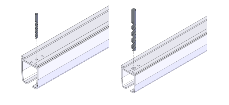
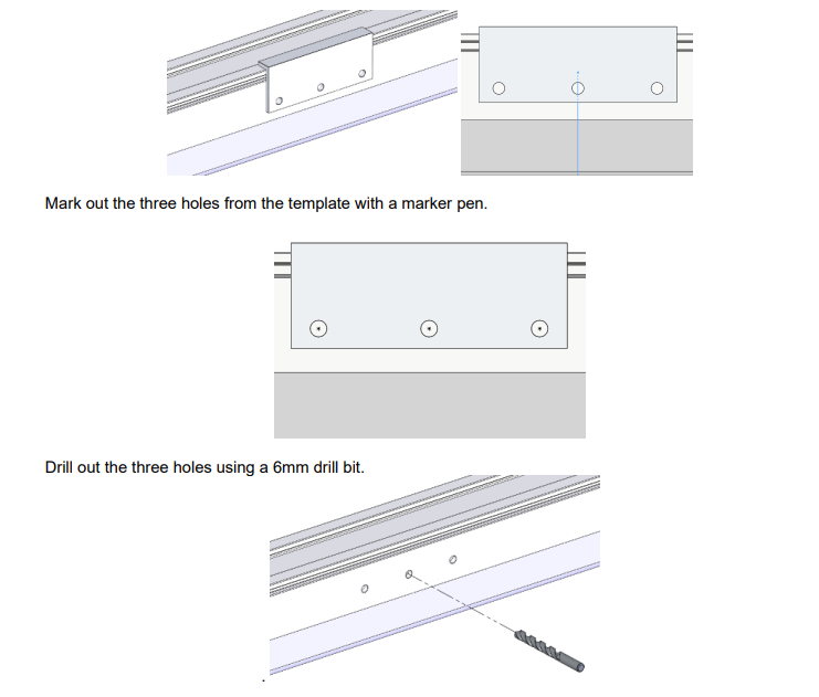
Using a marker pen, mark out the three holes from the template piece. Proceed to drill the three holes using a 6mm drill bit for the two outer holes and a 13mm drill for the center hole.
Using a combination between a file and a deburring tool, tidy up all the drilled holes.
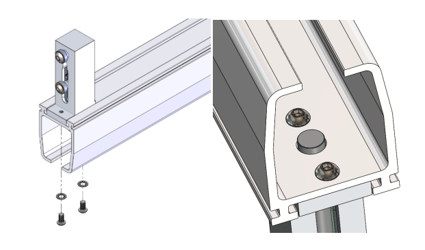
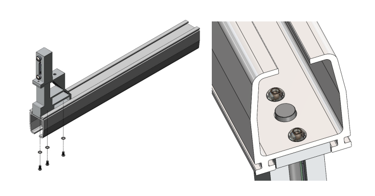
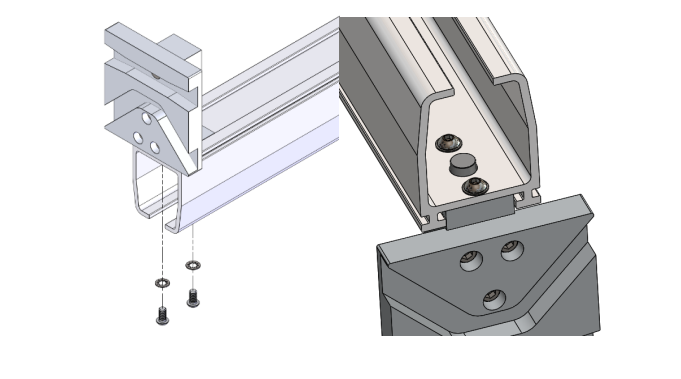
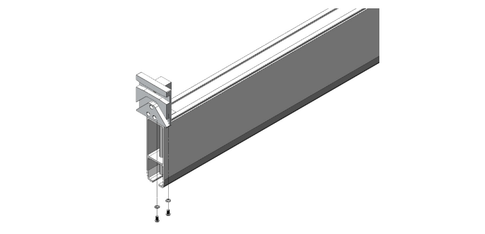
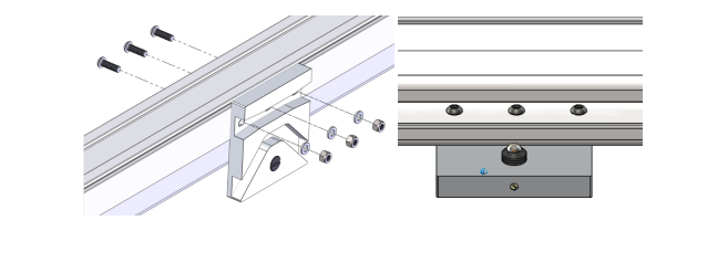
Align the fixed track transition gate block with the drilled holes, the safety bolt should be placed through the 13mm hole. See image below for correct orientation.
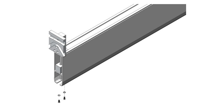
Secure the fixed track transition block using the given M6 screws and washers, these should be fitted inside the track as shown using a 4mm Allen key.
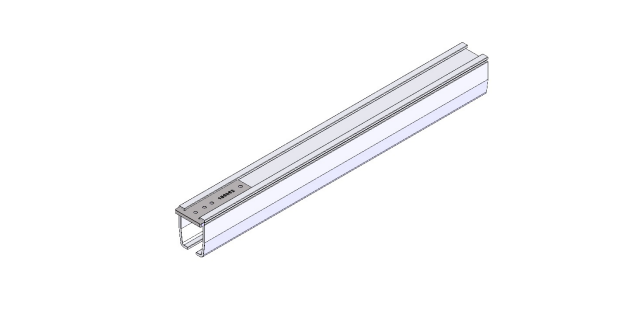
The fixed track transition gate block is now fitted onto the fixed track.
The fixed track can be installed onto the ceiling following the track installation section. Refer to section 10.0
9.1.2 Fixed Track Transition Gate Assembly (Heavy Duty Transition Gate)
Starting with the fixed track piece, a template piece with “100062” engraved onto it must be placed on the top of the track as shown in the image below.
Using a marker pen, mark out the four holes from the template piece. Proceed to drill the first, third and fourth hole using a 6mm drill bit, the second hole must be drilled to a diameter of 13mm.
Using a combination between a file and a deburring tool, tidy up all the drilled holes.
Align the fixed track transition gate block with the drilled holes, the safety bolt should be placed through the 13mm hole. See image below for correct orientation.
Secure the fixed track heavy duty transition block using the given M6 screws and washers, these should be fitted inside the track as shown using a 4mm Allen key.
The fixed track heavy duty transition gate block is now fitted onto the fixed track.
The fixed track can be installed onto the ceiling following the track installation section. Refer to section 10.0
9.1.3 Moving Track Transition Gate Assembly (Standard Transition Gate)
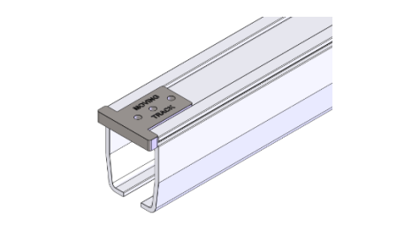
For the moving track, place the “moving track” template onto the top face of the track as shown in the mage below.
Using a marker pen, mark out the three holes from the template piece. Proceed to drill the three holes using a 6mm drill bit for the two outer holes and a 13mm drill for the centre hole.
Using a combination between a file and a deburring tool, tidy up all the drilled holes.
Align the moving track transition gate block with the drilled holes, the safety bolt should be placed through the 13mm hole. See image below for correct orientation.
Secure the moving track transition plate using the given M6 screws and washers, these should be fitted inside the track as shown using a 4mm Allen key.
The moving track transition plate is now fitted onto the moving track
The moving track can be installed onto the h-system parallel tracks following the h-system moving track installation. Refer to section 8.2.
9.1.4 Moving Track Transition Gate Assembly (Heavy Duty Transition
Gate)
For the moving track, place the “moving track” template onto the top face and inner face of the track as shown in the image below.
Using a marker pen, mark out the three holes from the template piece. Proceed to drill the three holes using a 6mm drill bit for the two outer holes and a 13mm drill for the centre hole.

Using a combination between a file and a deburring tool, tidy up all the drilled holes.
Align the moving track heavy duty transition gate block with the drilled holes, the safety bolt should be placed through the 13mm hole. See image below for correct orientation.
Secure the moving track transition plate using the given M6 screws and washers, these should be fitted inside the track as shown using a 4mm Allen key.
The moving track transition plate is now fitted onto the moving track.
Place the transition gate guiding block onto the top face of the inner track profile as shown. This is secured from below using the given M6 screws and washers, use a 4mm Allen key to secure.
The moving track can be installed onto the h-system parallel tracks following the h-system moving track installation. Refer to section 8.2.
9.1.5 Parallel Track Transition Gate Assembly
This section can only be followed once all tracks have been installed to the ceiling, this includes the fixed track, the two parallel tracks and the moving track. The placement of parallel track transition plate must be aligned perfectly central with the centre of the fixed track, this can be done using a laser. Mark out the alignment on the track using a marker pen.
The parallel track template piece centre hole must be aligned with the marked line as shown.
Using a combination between a file and a deburring tool, tidy up all the drilled holes.
Align the parallel track transition gate plate with the drilled holes. Secure the plate with the given M6 screws, washers and M6 nyloc nuts. See image below for correct orientation.
The ball bearing must be adjusted to suit the h-system trolley to allow the locking system to function. The ball bearing can be adjusted from the front using a flat screwdriver. Adjust until the contact point is secure when using the transition gate. Too tight will not allow the transition gate to traverse, while too loose will not lock in position when the transition is in use. The small grub screw shown in the second image below is used to lock the position of the ball bearing adjustment. See images below.
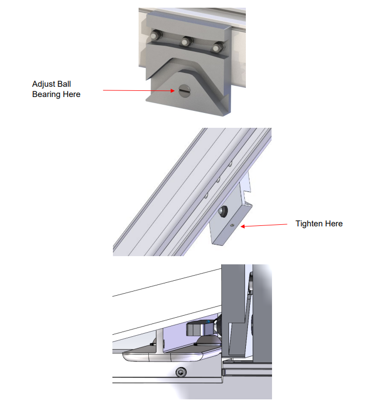
The adjustment of the ball bearing to contact the trolley must be done while the moving truck is under maximum load to ensure that the system is functioning correctly
The transition gate assembly is complete.