The single track, double track, heavy-duty track and inset tracks are all installed in the same fashion shown below. The only difference being the amount of fixings required. This can be determined by referring to the table in section 1.1 – straight track fixing instructions.
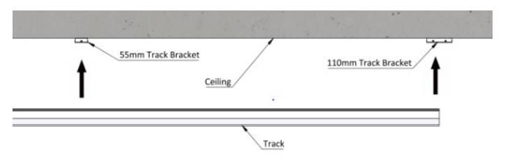
Raise the track and align the top face with the track brackets as shown, ensure that each track bracket aligns perfectly with the track.
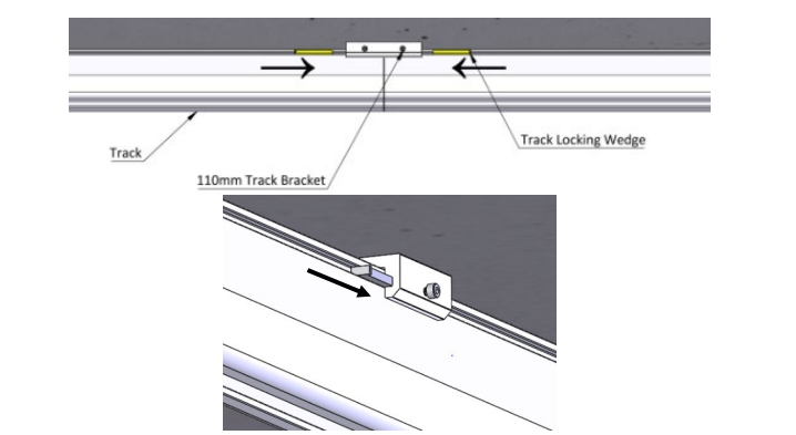
Once the track is aligned, the track locking wedges are required to secure the track, a total of two wedges must be fitted, one on either side as shown, and are inserted in the opposite directions.
Once the wedges have been fitted, the M3 screws on either side of the track bracket must be tightened to secure the track.
When two tracks are linking, they will both align at a double track bracket, they must evenly share the bracket and are fitted using four wedges. The same fitting process is used. See image below for reference.
The two linking tracks must be up against each other or not be further than 1mm apart. A total of four wedges are required to be fitted, two on either side of the bracket as shown.
Once the wedges have been fitted, the two M3 screws on either side of the track bracket must be tightened to secure the track.
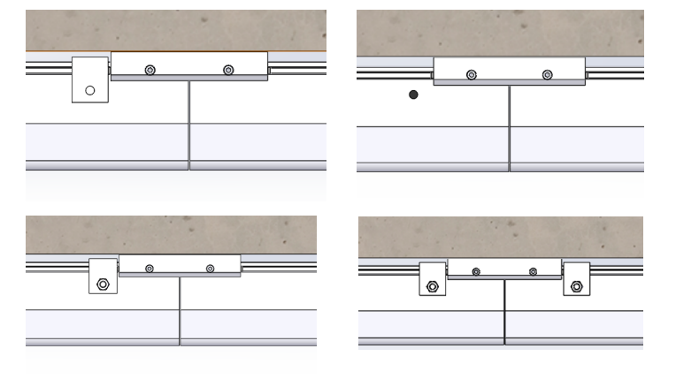
To finalise the track bracket fixing, a track lock plate is required for each installed track wedge. To fix the lock plate, align it up against the track bracket in the orientation shown in the diagram. The lock plate must be fixed against the face where the track wedge can be removed. Once the bracket is aligned, mark the centre hole onto the track using a marker pen. Drill the marked position out using a 6mm drill piece. Tidy the drilled hole using a deburring tool.
To secure the lock plate in position, place the M6x16mm screw through the hole and lock plate from within the track, and secure with the given nyloc nut. A 3mm Allen key and 10mm spanner are required.
10.1.1 Additional Requirements for Double Track Installation
The double track is two tracks being doubled up for additional strength to increase the maximum span between fixings. This track is usually used for h-systems.
The bottom half of the track is a standard single track and the track will be installed onto the track brackets following the same procedure as 10.1.
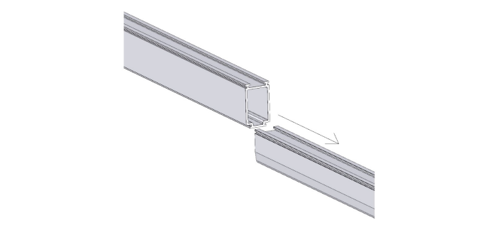
The top half of the track is to be installed onto the bottom track by sliding it onto its profile, as shown in the image.
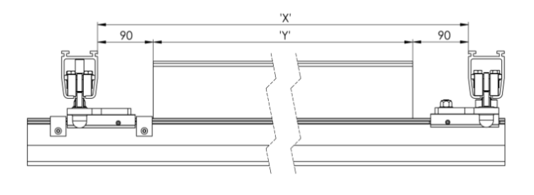
The top half-track must be cut shorter to allow the h-system trolley track bracket fixing to attach to the bottom track.
The top half-track should be cut to a length as close to the h-system trolley fixing brackets as possible, to provide maximum strength.
To determine the length the top half-track, the distance between the two parallel tracks of the h-system must be measured, and 180mm must be removed from this measurement to determine the length. See the image below for reference.
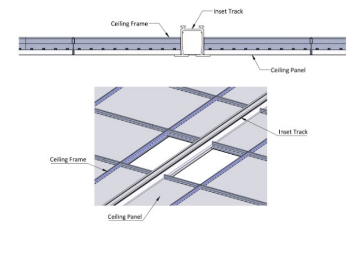
10.1.2 Additional Requirements for Inset Track
The inset track will be installed onto the track bracket in the same fashion as the single and heavy-duty track. The inset track is designed to allow the false ceiling tiles to sit on the bottom of the track as shown below. Follow the procedure below to install the inset track.
1. Remove the necessary false ceiling tiles as to access the track brackets.
2. Follow section 10.1 to install the track to the brackets.
3. The false ceiling tiles must be placed onto the track.
4. Cut the false ceiling tiles to size to fit them neatly onto the track.