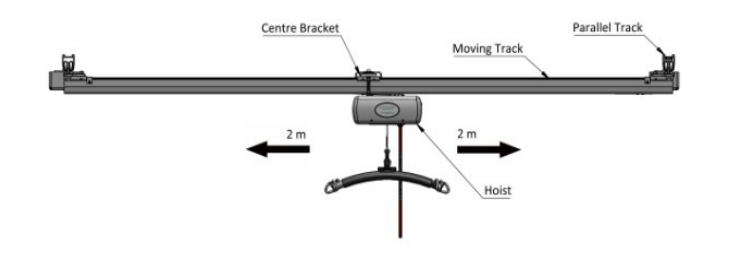
The powered h-system is an option of an h-system that can be driven using the hoist handset, the hoist handset is provided with traversing buttons which traverse the h-system back and forth along the parallel tracks. The powered h-system is only suitable for a 4m moving track span, as the hoist cannot traverse further than 2m either side of the centre bracket. The h-system must not allow a larger travel distance for the hoist, this can be ensured by either installing a 4m wide h-system or placing end stop 4m apart from the centre point of the track.
8.3.1 Powered H-System Additional Fixings
The powered h-system requires additional fixings over the manual h-system, see the fixing methods below for powered h-system.
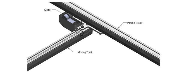
The two trolleys are provided with driving motors to allow the moving track to traverse. The driving motors must be facing inward towards the moving track when installed. This will allow for a wider h-system when installing up against a wall.
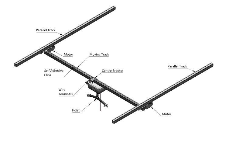
The powered h-system will be fitted with a centre bracket which is the connection point for the hoist communications cable and the traversing motors, the bracket is fixed onto the track in the same fashion as a standard track bracket, place the centre bracket at the centre of the moving track, this will allow the
maximum traversing distance for the hoist. The top plate on the centre bracket should be orientated to suit the hoist, i.e. The closest orientation to the communications port.
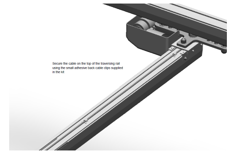
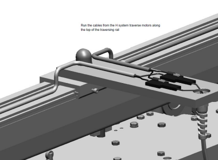
The wires from the two trolley motors must now be routed along the top of the moving track into the connector ports. The wires can be secured on the top face of the moving track using self-adhesive clips.
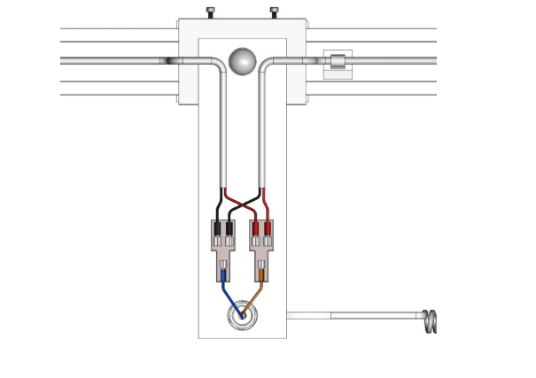
When the motor wires reach the centre bracket, they both split into two connector wires, these will plug into their separate connector ports. The red wires for the individual motors can go into either of the connector ports, while the black will go into the other port, these wires must not be mixed.
Once the motor wires are plugged into the ports, the hoist can be inserted into the moving track and placed at the centre of the track.
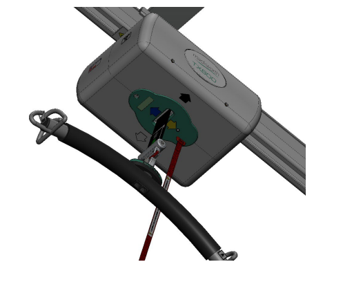
The hoist communications port must be attached to the centre bracket, remove the plastic nut on the communications port and place the port through the centre bracket fixing point, secure the port by reattaching the plastic nut onto the port.
The communications port wire splits into two connectors, attach the brown wire to the red wire connector port, and the blue wire to the black wire connector port. See the image above.
On the underside of the ceiling track hoist, there will be a black and white arrows showing the direction of travel for the moving track, these arrows should correspond with the hoist handset activation, ensure that when the handset is operated, the powered h-system will traverse in the correct direction.