When a fixing is required to be installed onto a sloping roof, the standard fixing methods will not suffice. The swivel fixing method allows the track bracket fixing point to swivel and realign vertically for a suitable fixing to the ceiling. The swivel fixing assembly can be fitted onto joists which run parallel, diagonal and perpendicular with the track. (when fixing parallel, the fixings cannot exceed the steel channel maximum spans, see section 1.4.2 for details). The swivel fixing assembly can only be fitted directly into the joists from below and will use coach bolts to secure. See the guidance below for the fixing method of the swivel assembly. Ensure to refer to section 3.1 to predetermine the fixing positions of the track brackets into the joist before proceeding with this section, it is not necessary to drill the pilot holes from section 3.1 as the location is incorrect. Simply mark out the centre point.
1. From the track bracket centre point marked on the ceiling, the two coach bolts must be fixed either side. Depending on any obstacles, mark out fixing positions on the ceiling. The two fixings are ideally fixed between 250mm and 600mm from each other. But it is acceptable for them to go up to 1000mm if necessary.
2. A laser should be used to ensure that the marked-out positions are in line with the centre hole.
3. Using a drill, pilot holes must be drilled into the joist using an 8mm drill bit to a depth of 90mm.
4. Once the holes have been drilled, they must be cleaned out, a hoover, air gun or hole brush will suffice.
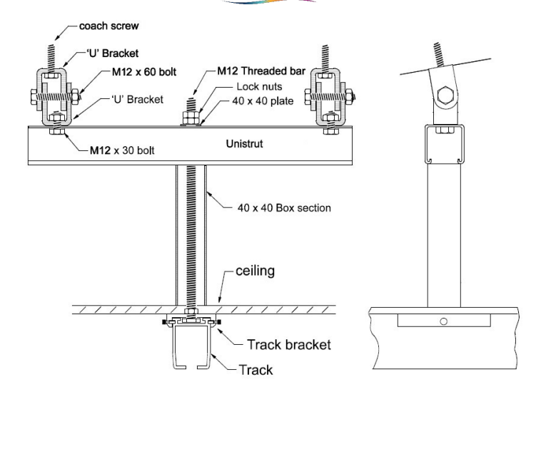
5. Place a u-bracket onto a coach bolt and secure the 12.0x100mm coach bolt into the joist. Repeat this for both fixing points.
6. Align the u-bracket in the opposite orientation as the fixed u-bracket and place a bolt through the two brackets and secure using an M12 nyloc nut. See image below for reference. Repeat this for both fixing points. Do not fully tighten the two brackets together.
7. Angle the lower u-bracket vertically, to allow the track bracket to align horizontally. Once the angle has been determined, the bolt can be secured tight to disallow rotation.
8. Depending on the gap size between the two fixings, a piece of steel channel must be cut to a suitable length. If the gap size is between 250mm and 600mm, a single piece of steel channel will suit. If the gap size is between 600mm and 1000mm, a piece of double steel channel must be used and cut to a suitable length.
9. Place the steel channel up against the u brackets and place an M12x30 bolt through the steel channel and secure inside the u bracket with an M12 nut.
10. A piece of threaded bar must now be cut to length to suspend the track bracket from the steel channel to the ceiling. Each threaded bar will vary in length depending on the joist and ceiling height. Ensure to allow additional thread for the fixings.
11. A piece of 40×40 box section must be cut to length to fit from the bottom of the steel channel to the top face of the track bracket.
12. Insert the threaded bar through the steel channel, lock the threaded bar off at the top by placing a fish plate, full nut and nyloc nut onto the steel channel.
13. Place a fish plate up against the underside of the steel channel.
14. From the centre of the ceiling fixing hole, the 40×40 box section profile must be cut out.
15. Place the box section through the ceiling and onto the threaded bar, the box section should become flush with the steel channel and the ceiling.
16. Attach a track bracket (either a single 55mm threaded hole or a double 110mm bracket threaded hole depending whether the bracket is securing a single track or two joining tracks) to the end of the threaded bar, and secure with a M12 half nut at the ceiling end, applying loctite 270 to the half nut.
17. The track bracket should become flush with the ceiling and box section.