9.19 Communications Port
Within this section it will explain the correct procedure on removing and reinstalling the Communications Port for servicing procedures or replacement.
Removal
Step 1 – Remove external covers off the Hoist. (Refer to section 9.1)
Step 2 – Remove the Battery from the battery brackets. (Refer to section (9.3)
Step 3 – Disconnect the Communications Port from the PCB.
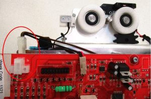
Step 4 – Reroute the Wire from behind the PCB and from under the opposite sides battery bracket.
Step 5 – Cut the three cable ties that secure the wire to the Chassis.
Step 6 – Using a 2mm Allen Key, Remove the M3x12 Screws and M3 Nyloc Nuts to release the Charging Beak.
Refitting / Replacement
Step 7 – Refitting is a reversal of the removal process noting the following point:
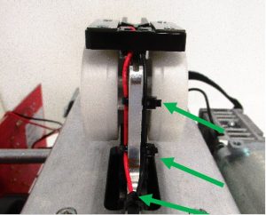
Three cable ties are required! – Re-secure the Wire with cable ties as instructed below:
A1) Insert the cable tie (100mm x 2.5mm) through the top hole in the Chassis plate and along the back of the red and black wires.
A2) Fold the cable tie around the Black wire and pass the cable tie back through the hole and over the Red wire.
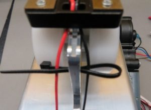
A3) Tie the cable tie retaining the Black wire and Red wire.

A4) Repeat this process for the second cable tie. For the bottom hole a cable tie 100mm x 2.5mm can be passed through the hole then around the Black and Red wires and tied off. Finally, snip of the surplus cable once secured.
