9.9 Hub
This section will instruct the correct procedure on how to remove and replace the Hub.
Removal
Step 1 – Remove external covers off the Hoist. (refer to section 9.1)
Step 2 – Remove the PCB from the Hoist. (refer to section 9.2)
Step 3 – Remove the Battery from the battery brackets. (refer to section (9.3)
Step 4 – Remove Lift Motor. (Refer to section 9.5)
Step 5 – Remove Bottom Cover. (Refer to section 9.7)
Step 6 – Remove Lift Tape. (Refer to section 9.10)
Step 7 – Remove Air Tube Grommet (refer to section 9.15)
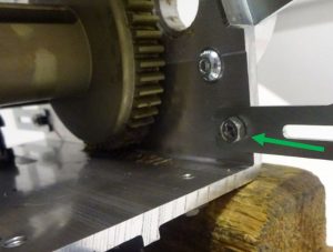
Step 8 – Using an 8mm spanner, loosen the M5 x 12 screw (arrowed) – The screw is not required to be removed. (This is the Battery Bracket beside the Air Grommet)

Step 9 – Using an 8mm spanner or a Pozi screw driver remove the M5 x 8 screw (arrowed) from the chassis.
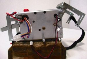
Step 10 – Pivot the battery bracket to its maximum height.
Step 11 – Using a 4mm Ball point Allen Key, remove the three M6 x 16 over speed screws.

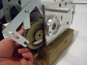
Step 12 – Support the Hub with your hand, while removing the strap pin.

Step 13 – Slowly guide the Hub out of the chassis. (As shown below)

Refitting / Replacement
Step 14 – Refitting is a reversal of the removal process noting the following point:
1. If replacing Hub, grease with Morris Grease – K42EP multi-purpose.
2. When inserting the Hub back into the Chassis make sure the orientation is correct. The Over-Speed Cam must face the Lift Motor side of Chassis.