9.16 Toggle switch
This section will instruct the correct procedure on how to remove and replace the Toggle Switch.
Removal
Step 1 – Remove external covers off the Hoist. (refer to section 9.1)
Step 2 – Remove the Battery from the battery brackets. (refer to section (9.3)
Step 3 – Remove QRS Hook. (Refer to section 9.6)
Step 4 – Remove Bottom cover from Hoist. (Refer to section 9.7)
Step 5 – Remove the E-Lower Cord. (Refer to section 9.17)
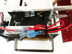
Step 6 – Disconnect the Toggle Switch from the PCB.

Step 7 – Disconnect the Motor wires from the Toggle Switch
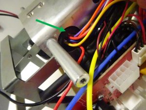
Step 8 – Using Snips, cut the cable ties to release the Toggle Switch wires, see image above for guidance on location.
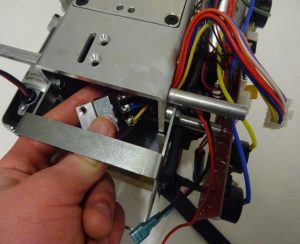
Step 9 – Using as small flat head screwdriver, detach the grommet (arrowed) from the chassis by forcing it through the hole.
Step 10 – Pull the Toggle Switch from within the Chassis to remove.

Refitting / Replacement
Step 11 – Refitting is a reversal of the removal process noting the following point:
1. Cable ties is required! – Reroute the Toggle Switch wires as shown in the image and cable ties into position, cut the surplus once secured.
