9.2.1 Powered Traverse PCB
This section will instruct the correct procedure on how to remove and replace the Powered Traverse PCB, this procedure can also be used as guidance when servicing a Manual Traverse PCB. See section 9.2.2 instructions on removing a Powered Auxiliary Hoist PCB.
Removal
Step 1 – Remove external covers of the Hoist. (Refer to section 9.1)
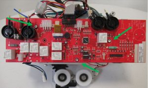
Step 2 – Remove the Power supply cable, by pressing down on the latch and then pull perpendicularly away from the PCB. (Arrowed)

Step 3 – Remove the remaining connectors in the numerical order labelled below.
1. Toggle switch
2. Limit switch
3. LCD/Display
4. LED
5. Traverse Motor
6. Charging Beak

Step 4 – Remove the colored air tubes (Grey and Green) by gently pulling on the air tubes individually until they release from their individual air switches on the PCB.
Step 5 – Using a 2.5mm Allen key remove the three M3 screws. (arrowed)
Step 6 – Remove the PCB from the Hoist.
Refitting / Replacement
Step 7 – Refitting is a reversal of the removal process noting the following points:
1. Make sure the power cable is connected last.
2. Air tubes to be fully pushed onto air switches.
3. Check for any holes within the air lines.
9.2.2 Powered Auxiliary PCB
This section will instruct the correct procedure on how to remove and replace the Powered Auxiliary PCB.
Removal
Step 1 – Remove external covers of the Hoist. (Refer to section 9.1)
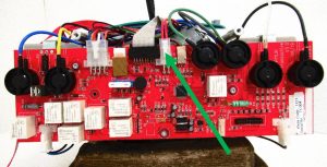
Step 2 – Remove the Power supply cable, by pressing down on the latch and then pull perpendicularly away from the PCB. (Arrowed)
Step 3 – Remove the remaining connectors in the numerical order labelled below.
1. Toggle switch
2. Limit switch
3. LCD/Display
4. LED
5. Traverse Motor
6. Charging Beak
7. Communications Port

Step 4 – Remove the colored air tubes (Grey, Green, Yellow, Blue, White and Black) by gently pulling on the air tubes individually until they release from their individual air switches on the PCB.
Step 5 – Using a 2.5mm Allen key remove the three M3 screws. (Arrowed)
Step 6 – Remove the PCB from the Hoist.
Refitting / Replacement
Step 7 – Refitting is a reversal of the removal process noting the following points:
1. Make sure the power cable is connected last.
2. Air tubes to be fully pushed onto air switches.
3. Check for any holes within the air lines.