9.8 Limit Switch
This section will instruct the correct procedure on how to remove and replace the Limit Switch Block.
Removal
Step 1 – Remove external covers off the Hoist. (refer to section 9.1)
Step 2 – Remove the PCB from the Hoist. (refer to section 9.2)
Step 3 – Remove the Battery from the battery brackets. (refer to section (9.3)
Step 4 – Remove the Lift Motor. (Refer to section 9.5)
Step 5 – Remove Lift Tape. (Refer to section 9.10)
Step 6 – Remove Bottom Cover. (Refer to section 9.7)
Step 7 – Using a slotted screw driver, prise the grommet (arrowed) from the chassis.
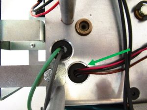
Step 8 – Guide the Limit Switch Wires and Connector into the Chassis.

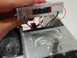
Step 10 – Once all four screws have been removed, slide your hand inside the Hoist and push the limit switch block upwards.
Ensure not to trap the wires while removing the Limit Switch Block.

Step 11 – While guiding the limit switch block out of the chassis, carefully guide the wiring loom out with the unit.
Refitting / Replacement
Step 12 – Refitting is a reversal of the removal process noting the following point:
1. When placing the Limit switch up to the chassis make sure the orientation is correct

Risk of trapping wires highlight by red circle.
2. After rerouting the wires make sure you pull the wiring back through the hole to reduce the slack inside the chassis, and refit the grommet.
